Set a Video Source on the Encoder for Live Streaming
Begin by setting a video source on the encoder. You will select how your device is connected, its input, and other relevant attributes. This will include setting a video template and video rate settings as well.
1. Navigate to Encoder Configuration > Video (labeled Video Input on some models).
The vbrick encoder supports the Baseline, Main, and High profiles and provides superior performance under a wide variety of network and application environments. H.264 video compression will typically provide the same quality as MPEG‑2 at half of the bit rate or less, especially in high bit rate and high resolution environments. For more information about 9000 Series encoders and decoders, go to the www.Vbrick.com\products page on the Vbrick website.
When making configuration changes, the slot shown in bold (see Figure 1 below) is the currently selected slot, an asterisk (*) next to the Slot/Channel header near the top of the page indicates there are pending changes to the configuration which have not yet been “applied,” and a red exclamation point indicates a configuration error in that slot.
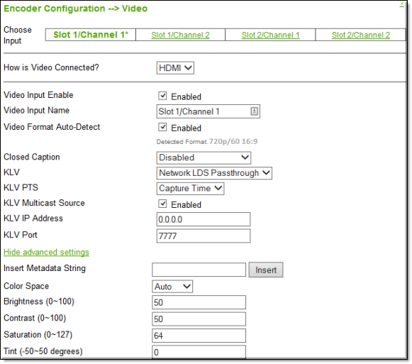
Figure 1. Video Configuration: Part 1 – Video Input
Keep in mind that any currently active streams will be momentarily disrupted every time you click Apply. To avoid intermittent disruptions on units with multiple slots and channels, wait until you have configured changes on all slots and channels, and then click Apply. This behavior only applies to the Encoder Configuration > Video and Audio pages. On all other pages you must click Apply before you exit the page.
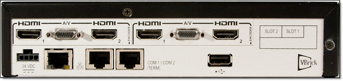
Figure 2. Quad Channel Encoder (no SDI)
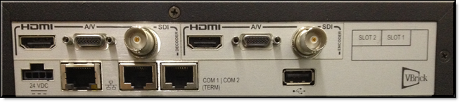
Figure 3. Dual Channel Encoder (with SDI)
Tip: The fields described below relate to using Vbrick devices with Rev specifically. As a result, not all available fields are covered in their entirety here. For a full description of encoder device setup, view the vbrick encoder Online help. |
Field | Description |
|---|---|
Choose Video Input | Choose the video input to configure. Your encoder may be configured with one slot or two slots, with one or two channels in each slot. Figure 3 shows an encoder with two slots (and four channels). As shown in the graphic (at the right side on back of unit) Slot 1 is physically on the right; Slot 2 is on the left. ●Slot1/Channel 1 ●Slot1/Channel 2 ●Slot2/Channel 1 ●Slot2/Channel 2 |
How is Video connected? | Figure 3 shows the High Definition video input connectors on the rear panel. The A/V connector on the unit is used with the Vbrick‑supplied "breakout" cable which has both Composite and Component video inputs. Select the option from the dropdown that matches your video input. ●Composite – one connector (labeled COMP IN) on breakout cable. Use the Micro DB-15 connector (located between the two HDMI ports). ●Component – three connectors (labeled Y, Pb, Pr) on breakout cable. Use the Micro DB-15 connector (located between the two HDMI ports). ●HDMI – High Definition Multimedia Interface that transmits uncompressed digital data. ●SDI – supports both SD-SDI typically used for broadcast-grade video (meets SMPTE 259M) or HD/3G-SDI which processes 1080p at bit rates of 2.97 Gbits/sec (meets SMPTE 424M). ●VGA – supports most of the common analog output videos from a PC or laptop. |
Video Input Enable | Use to Enable|Disable the selected Video Input. All video inputs are enabled by default. |
Video Input Name | Used to provide a meaningful name to the video input source such as “Camera 1" or “Rear Camera”. The default value of the field is useful to understand the physical connection while renaming the field will convey what video source will be visible. |
Video Format Auto Detect | Used to auto detect the format being used. If a supported format is in use, video format and aspect ratio will be auto-detected and used. The drop-down menus for those values will not appear as a result. |
Video Format | This field is displayed if Video Format Auto Detect is not enabled and is used to configure the Video Format on the encoder so that it exactly matches the video source connected to the encoder. As an aid, the encoder can sense the input format and report it in the Detected Video Format read-only field. The options for Video Format shown below vary depending on how the input video is connected. ●Composite – NTSC. PAL. ●Component – 1080p/60/30, 1080i/60/50, 720p/60/50, 576p/i, 480p/i, 1400x1050/60, 1280x1024/60, 1366x768/60, 1360x768/60, 1280x768/60, 1024x768/60, 800x600/60 ●HDMI – 1080p/60/50/30, 1080i/60/50, 720p/60/50, 576p/i, 480p/i, 1280x1024, 1024x768, 800x600, 640x480 ●SD-SDI – 576i, 480i ●HD/3G-SDI – 1080p/60/50/30, 1080i/60/50, 720p/60/50 ●VGA - 1600x1200/60, 1680x1050/60, 1400x1050/60, 1280x1024/60, 1366x768/60, 1360x768/60, 1280x768/60, 1024x768/60, 800x600/60, 640x480/60 |
Video Aspect Ratio | Video Aspect Ratio is the ratio of the width of the image to the height of the image. High Definition video generally uses 16:9; Standard Definition uses 4:3. This field is not displayed and automatically detected if Video Format Auto Detect is enabled. |
Detected Format | Shows the detected Video Format (see Figure 1) and Aspect Ratio that is actually connected. |
Color Space | (Advanced Setting) HDMI/Component. Override the default Color Space. Useful if connecting DVI from a PC over HDMI. The encoder autodetects and supports both YCrCb (commonly used by cameras or video players) and RGB (commonly used by computers) on the HDMI and Component inputs. ●Auto – Default. ●RGB – represents the color space as red, green and blue. ●YCrCb – represents the color space as luminance (Y) and color difference signals (R-Y) and (B-Y). In most situations and with most video devices, the default setting to Auto detect the Color Space is recommended. However with some types of video equipment like DVI‑to‑HDMI convertors and general purpose image scalers, the encoder's automatic setting may not be able to choose correctly. If you see a pink or green tint on the encoded video there is a good chance the color space of your source and the encoder do not match. |
Brightness | (Advanced Setting) 0–100. Default = 50. Brightness is information about the varying light intensity of an image which is best described as brightness. It only affects the luminance (Y) component of the color space. |
Contrast | (Advanced Setting) 0–100. Default = 50. The contrast is the range of light-to-dark values of an image that are proportional to the voltage differences between the black and white levels of the signal. |
Saturation | (Advanced Setting) 0–127. Default = 64. Saturation is the spectral intensity of a color. It operates on the PbPr (CbCr) chroma components of the color space by increasing or decreasing both components by the same percentage. |
Tint | (Advanced Setting) +50/-50 degrees. Default = 0. Tint (or Hue) is the attribute by which a color may be identified in the visible spectrum and refers to the chromaticity of the image. Adding or subtracting Tint changes the color (Hue) of the video. The numbers actually relate to the vector phase of the color spectrum in degrees of a total of ± 180 degrees. |
Blackout Top | (Advanced Setting) 0–2. Default = 0. Available with 480i and 576i inputs only. Some video signals include additional information that results in undesirable artifacts on some sides of the video frame. This option blacks out an area near the top of player window—not a specific number of lines. Be sure to test your results when using this option. |
Video Template Settings
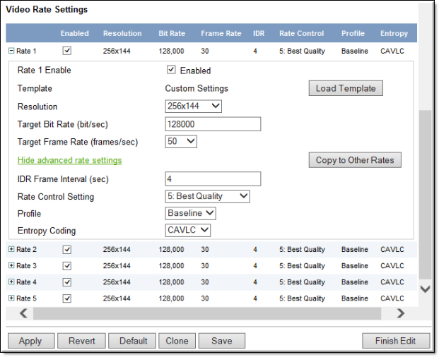
1. Navigate to Encoder Configuration > Video (labeled Video Encode on some models) > Video Rate Settings section.
2. Click the (+) expand icon to access additional fields and settings and advanced rate setting fields per setting. (You may need to click the Edit button first)
3. Click the Load Template button to load a template for a specific setting.
Use the Load Template button to populate the Video Template Settings with preconfigured video values (or select None). The templates available when you click Load Template will vary depending on your encoder model (1, 2, or 4 channels).
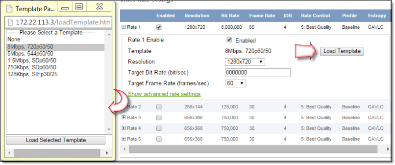
Choose a template based on motion and bandwidth. 750Kbps, SDp60/50 is the default template for a single or dual unit. Quad is 750Kbps, SDp30/25. To read the following table, start in left column and read from left to right.
Table 1. Video Template Settings
Template Name | Profile | Resolution 16:9 (4:3) | Bit Rate | Frame Rate | IDR | Rate Control | Entropy |
|---|---|---|---|---|---|---|---|
12Mbps,1080p60 | Baseline | 1920x1080 | 12M | 60(50) | 4 | 5 | CAVLC |
10Mbps,1080p60 | Baseline | 1920x1080 | 10M | 60(50) | 4 | 5 | CAVLC |
10Mbps,1080p30 | Baseline | 1920x1080 | 7M | 30(25) | 4 | 5 | CAVLC |
8Mbps,720p60 | Baseline | 1280x720 | 8M | 60(50) | 4 | 5 | CAVLC |
7Mbps,720p60 | Baseline | 1280x720 | 7M | 60(50) | 4 | 5 | CAVLC |
7Mbps,720p30 | Baseline | 1280x720 | 7M | 30(25) | 4 | 5 | CAVLC |
5Mbps,544p60 | Baseline | 960x544 | 5M | 60(50) | 4 | 5 | CAVLC |
4Mbps,544p60 | Baseline | 960x544 | 4M | 60(50) | 4 | 5 | CAVLC |
4Mbps,544p30 | Baseline | 960x544 | 4M | 30(25) | 4 | 5 | CAVLC |
1.5Mbps,SDp60 | Baseline | 656x368 (640x480) | 1.5M | 60(50) | 4 | 5 | CAVLC |
1.5Mbps,SDp30 | Baseline | 656x368 (640x480) | 1.5M | 30(50) | 4 | 5 | CAVLC |
750Kbps,SDp60 | Baseline | 656x368 (640x480) | 750k | 60(50) | 4 | 5 | CAVLC |
750Kbps,SDp30 | Baseline | 656x368 (640x480) | 750k | 30(25) | 4 | 5 | CAVLC |
128Kbps,SIFp60 | Baseline | 256x144 (192x144) | 128k | 60(50) | 4 | 5 | CAVLC |
128Kbps,SIFp30 | Baseline | 256x144 (192x144) | 128k | 30(25) | 4 | 5 | CAVLC |
Video Rate Settings
1. Navigate to Encoder Configuration > Video (labeled Video Encode on some models) > Video Rate Settings section.
2. Click the (+) expand icon to access additional fields and settings and advanced rate setting fields per setting. You may need to click the Edit button first.
The encoder supports multiple bit rate encoding (MBR). This means the encoder can encode one input stream at multiple bit rates that can be optimized and targeted for different devices. For example HD-TVs, PCs, and smartphones have different bandwidth requirements and will be associated with different streams. Each configured stream must be configured with a specific video and audio rate.
Note: There are five video rates available per input channel and a maximum of 16 video rates can be configured per unit. Be sure to review the MBR rules and constraints in the Vbrick Encoder Release Notes. |
Field | Description | |
|---|---|---|
Rate & Enable | Rate 1 is enabled by default. At least one rate must always be configured. | |
Template | This read-only field shows the template (if any) that is currently applied. The templates provide an optimized combination of settings that have been configured and tested at Vbrick. The templates available when you click Load Template will vary depending on your encoder model (1, 2, or 4 channels). See Table 1 on page 195 for a list of all templates and settings. If a template is applied it will display the template name (e.g. 750Kbps, SDp30/25) or Custom Settings (if you made changes after initially selecting a template). Select Load Template > None to clear a "Custom Settings" message. Select Copy to Other Rates to copy the "Advanced Rate Settings" only for the selected rate to all of the other rates on the same Slot and Channel. | 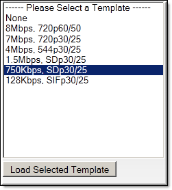 |
Resolution | Sets the video encoding resolution (the width and height respectively) of the compressed video stream. The Vbrick encoder has high quality video up/downscaling built-in to let you choose from a wide range of standard encode resolutions regardless of the Video Format of your source video. For example, you can use a 1080p60 High Definition video input source and have the encoder downscale the video to a Standard Definition resolution so it can be streamed with good quality at bit rates to match your network or to match the processing power and display resolution of your decoders, STBs or PC players. When the aspect ratio of the encode resolution does not match the aspect ratio of the input, the encoder will letterbox. Available video resolutions include: 1920x1080, 1680x1050, 1680x1008, 1600x1200, 1400x1050, 1366x768, 1360x768, 1344x1074, 1280x1024, 1280x768, 1280x720, 1120x700, 1024x768, 960x544, 832x666, 832x520, 832x500, 800x600, 720x576, 720x480, 656x410, 656x394, 656x368, 640x480, 512x288, 400x304, 384x288, 352x288, 352x240, 320x240, 256x144, 192x144, 176x128, 176x144, 128x96. | |
Target Bit Rate (bits/sec) | 32,000–20,000,000 bits/sec. Constant bit rate. Default = 750,000. This number can only be changed in 1000 bits/sec increments. It represents how much data the encoder will send out each second to carry video to a player. The word target is used because the encoder can vary its bit rate slightly in response to the amount of detail in the movie or camera output. The more data the encoder sends in one second, the more clearly the details of the video will be seen on a player. It is not always desirable to send the most possible data, since that requires a large network "pipe" (connection). The trade-off is the level of detail in the video with the use of smaller network connections. The encoder tries to encode the video at a quality that will (on average) match the Target Bit Rate. The larger the number, the better the quality but this can potentially limit the number of clients that can connect to the encoder. | |
Target Frame Rate (frames/sec) | The following options for Target Frame Rate vary depending on the Video Format selected above. There are specific Frame Rates associated with Standard Definition formats (NTSC or PAL) or with High Definition formats (all others). The default is based on the model: 60 (for single and dual channel models) or 30 (for quad channel models). ●NTSC – 60, 30, 24, 15, 10, 7.5, 6, 5, 3, 2 ●PAL – 50, 25, 12.5, 5, 2.5 Note: For Presenter Mode all of the above rates are allowed. This number represents how many frames the encoder will send out each second to carry the video to an H.264 player. The word target is used because the encoder can vary its frame rate slightly in response to the amount of motion in the movie or camera output. See the Rate Control Setting parameter below for more details. Frame rate is the number of "frames" the encoder sends in a second for an H.264 player to display. Moving pictures are made up of a rapid series of "still" pictures that move so fast that the "illusion" of motion is produced. A frame is one such "still" picture. Regular TV programs in the U.S. run at about 30 frames in a second, and the more frames presented in a second, the smoother the motion contained within the video will appear. Encoding and transmitting a frame requires the use of data, so that, when considering a particular bit rate, sending more frames demands that each frame contain fewer fine details. | |
IDR Frame Interval (sec) | 0–30. Default = 4. Also called "key frame interval." The frequency in seconds at which IDR (Intra Dynamic Refresh) frames are inserted for Seek, Fast Forward and Rewind functionality. Higher values create fewer random access points and better compression efficiency. Lower values create more access points but with less compression efficiency. Zero means all frames are IDR frames. Vbrick recommends you do not set to zero because video quality is not generally acceptable and stream bandwidth may be excessive. | |
Copy to Other Rates | Click this button to copy the "advanced rate settings" (IDR Frame Interval, Rate Control Setting, Profile, and Entropy Coding) to all other configured rates. | |
Rate Control Setting | 1: Lowest Latency – 5: Best Quality. Default = 5. This parameter lets you trade off video quality versus the latency imposed by the encoder. A higher value provides better quality but more latency; a lower value provides less latency with a loss of quality. This parameter lets you trade-off video quality with how tightly rate control is imposed. A larger number increases the number of frames over which the target number of bits can be distributed. This means that the average bit rate, measured over small periods of time, can fluctuate more around the specified target bit rate. A smaller number will reduce the fluctuations around the target bit rate but will also reduce the ability of rate control to apply the bits to scenes which might be visually optimized by their application. In addition, when using the Custom transport mode (see Transport Stream Settings) and attempting to tune for lowest possible latency (minimal PTS-PCR Gap), it is useful to minimize the bit rate fluctuations by using a smaller value. In bandwidth‑restricted networks with little tolerance for bit rate fluctuations, or when tuning aggressively for minimum delay, a smaller value is recommended; otherwise, use a larger value or the default. | |
Profile | The profile defines the subset of bit stream features in an H.264 stream, including color reproduction and video compression. ●Use a High profile for streaming to Rev. | |
Entropy Coding | Use CABAC for streaming to Rev. | |